Top Optical Attenuator Manufacturers and Suppliers?

Choosing among the top Optical Attenuator manufacturers and suppliers requires more than comparing catalog prices. These components regulate optical power in fiber networks, laboratory instruments, and communication systems. A reliable supplier should explain attenuation accuracy, wavelength range, connector options, and operating temperature clearly.

Experienced buyers often examine fixed and variable designs separately. Fixed attenuators support stable power reduction at known levels. Variable models help technicians adjust signals during testing and network commissioning. Small details matter. A polished housing, clean connector end face, and secure labeling can prevent costly mistakes in the field. Suppliers with documented testing procedures usually offer stronger confidence than vendors relying on broad marketing claims.

This guide considers manufacturers through practical criteria, including insertion loss, return loss, repeatability, durability, and customization support. It also looks at certifications, production capacity, delivery consistency, and technical assistance after purchase. A supplier may provide excellent specifications but still struggle with communication or replacement service. That weakness deserves attention. Real-world performance can differ from a datasheet when connectors are contaminated, cables are bent, or equipment operates near its limits. Therefore, readers should verify test conditions and request representative samples before approving large orders. The recommendations aim to support engineers, distributors, and purchasing teams seeking dependable optical attenuation solutions. No ranking can fit every project. Network design, budget, fiber type, and installation conditions should guide the final decision.
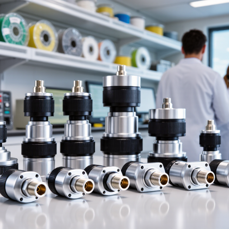
Top Optical Attenuator Manufacturers and Suppliers?

What Is an Optical Attenuator and How Does It Work?

An optical attenuator is a passive device that reduces light power in a fiber-optic link. It helps prevent receiver overload while preserving the transmitted signal’s basic pattern. Think of it as a controlled dimmer for invisible light.

Most attenuators use an air gap, absorbing material, or a carefully aligned optical path. Fixed models provide one loss value, such as 3 dB or 10 dB. Variable models allow technicians to adjust power during testing and commissioning. The device does not usually reshape the data; it lowers optical intensity. A clean connector remains essential. Dust can create more loss than the attenuator itself.

In practical installations, engineers check insertion loss, return loss, wavelength range, connector type, and power handling. They also compare measured power with the receiver’s operating limits. A simple power meter is often more reliable than visual inspection. I have found that specifications alone can mislead. Actual results may change with temperature, connector wear, and fiber movement. That detail is easy to overlook. Manufacturers and suppliers should provide traceable test data, clear tolerances, and compatibility guidance. Unclear labeling creates avoidable service work. For demanding links, technicians may test the attenuator before installation and again after the patch panel is connected.

Top Optical Attenuator Manufacturers and Suppliers? - What Is an Optical Attenuator and How Does It Work?

An optical attenuator reduces optical power by a specified amount without significantly changing the signal waveform. This chart shows the calculated output power from a 1 mW optical signal at different attenuation levels using the standard relationship: Pout = Pin × 10−A/10, where A is attenuation in decibels.

Main Types of Optical Attenuators and Their Applications

Optical attenuators control signal power without interrupting fiber transmission. Fixed attenuators deliver a predetermined loss, such as 3, 5, or 10 dB. They suit receiver protection, power balancing, and laboratory reference links. Their stable performance supports repeatable measurements at common wavelengths, including 1310 and 1550 nm. Small losses matter. Variable attenuators allow technicians to adjust power during testing. Manual models work well for occasional alignment, while motorized versions support automated test benches and production inspection.

Inline attenuators install between two fiber connectors or within a patch cable. They are practical for network upgrades where equipment output exceeds receiver limits. Bulkhead attenuators fit adapter panels and simplify dense rack installations.

In wavelength-division systems, wavelength-selective attenuators can balance individual channels more precisely. A lab-perfect setup may still fail in the field. Dust, connector wear, and temperature changes can alter the measured loss.

Programmable attenuators are useful for simulating real network conditions, including gradual signal reduction and protection thresholds. Test engineers often combine them with optical power meters and bit-error measurements. When selecting a supplier, check attenuation accuracy, return loss, operating wavelength, power handling, and polarization dependence. Check the calibration record. Reliable suppliers should provide traceable test data, clear connector specifications, and documented environmental limits. I have seen installations overlook connector end-face quality, then blame the attenuator for unstable readings. That mistake remains surprisingly common.

Key Standards for Evaluating Attenuator Quality and Performance

Top Optical Attenuator Manufacturers and Suppliers?

A reliable optical attenuator should meet measurable performance standards, not just present attractive specifications. Check attenuation accuracy across the intended wavelength range, especially at low settings. A device rated for 10 dB may behave differently at 850, 1310, and 1550 nm. It should also show insertion loss, return loss, polarization-dependent loss, and power-handling limits.

Use applicable IEC 61300 test methods when reviewing supplier data. These methods help assess insertion loss, return loss, environmental stability, and mechanical performance. Ask for calibration records with traceability to recognized measurement laboratories. Test reports should state equipment accuracy, temperature, connector type, and measurement uncertainty. Without these details, comparison becomes unreliable.

Repeatability matters in daily operation. Rotate a variable attenuator several times and record whether the reading returns to the same value. Test it after vibration, connector cleaning, and temperature changes. Fixed attenuators also need inspection for end-face quality and housing damage. A strong supplier explains test conditions clearly and provides samples for independent verification. Claims about lifetime should include cycle counts and environmental limits. No test plan is perfect. Real systems may expose weaknesses that laboratory checks miss. That is why field feedback, documented corrective actions, and responsive technical support should influence the final supplier decision.

Top Optical Attenuator Manufacturers and Global Suppliers

Global optical attenuator suppliers are serving a market shaped by higher fiber capacity and stricter power control. The 2024 Optical Communications Market Review by LightCounting links data-center expansion with sustained demand for optical components. Research and Markets also projects steady growth for the optical attenuator sector through 2030, although estimates vary by application and region. This variation matters.

Reliable manufacturers typically offer fixed, variable, inline, and connectorized attenuators. Their products may support single-mode systems, laboratory testing, or dense wavelength-division networks. Buyers should check attenuation accuracy, return loss, wavelength range, and operating temperature. IEC 61300-3-6 testing practices help evaluate reflectance and insertion loss. ITU-T recommendations can also guide system-level compatibility.

Global suppliers differ in more than factory location. Some provide short lead times from regional warehouses. Others offer stronger engineering support, custom packaging, or traceable calibration reports. A practical audit should examine production capacity, quality certificates, sample data, and failure records. Ask for test results at the actual operating wavelength. It prevents an uncomfortable surprise later. No supplier is perfect. Even a polished datasheet may hide connector variation, aging effects, or limited stock. This is where experience remains valuable: compare measured performance, not marketing language, before approving a long-term source.

Top Optical Attenuator Manufacturers and Suppliers? - Top Optical Attenuator Manufacturers and Global Suppliers

Supplier Category Common Attenuator Products Typical Wavelengths Typical Attenuation Range Typical Optical Power Common Connector or Interface Control Method Typical Applications
Passive fiber-component manufacturers Fixed fiber attenuators; plug-in attenuators; inline attenuators 850, 1310, 1490, 1550, and 1625 nm Usually 1–30 dB; common values include 3, 5, 10, 15, and 20 dB Often up to approximately +20 dBm, depending on design and wavelength LC, SC, FC, ST, and bare-fiber versions Passive; preset attenuation Receiver overload protection, power balancing, and link testing
Variable optical attenuator suppliers Manual variable attenuators; continuously adjustable optical attenuators Commonly 850, 1310, and 1550 nm; broadband models are also available Typically 0–30 dB or 0–60 dB, depending on model Generally from a few milliwatts to several hundred milliwatts LC, SC, FC, polarization-maintaining, and fiber-pigtail interfaces Manual screw, rotary control, or micrometer adjustment Laboratory measurement, calibration, receiver testing, and optical characterization
MEMS-based optical equipment suppliers Motorized variable optical attenuators; MEMS VOA modules; multi-channel VOA assemblies Typically C-band around 1525–1575 nm; some models support O-band and L-band Commonly 0–30 dB or 0–40 dB; higher ranges are available in selected designs Usually suitable for telecommunications signal levels and equipment test systems Fiber pigtails, LC connectors, ribbon fiber, or board-level electrical interfaces Electrical, digital, Ethernet, USB, or rack-controller operation ROADM systems, optical network monitoring, automated test equipment, and power equalization
Optical test-equipment suppliers Programmable attenuators; attenuator modules; integrated optical power-control units 850, 1310, and 1550 nm are the most common test wavelengths Often 0–60 dB with programmable step sizes as low as 0.01 dB Designed for controlled laboratory and production-test input levels Interchangeable FC, SC, or LC adapters; USB, LAN, or GPIB control Front-panel, remote software, LAN, USB, or GPIB Transceiver testing, BER testing, sensitivity testing, and manufacturing verification
High-power fiber-optic component suppliers High-power fixed attenuators; high-power variable attenuators; free-space attenuators Commonly 1064, 1310, 1550, and 2000–2200 nm, depending on application Usually 3–30 dB; customized ranges may be available From hundreds of milliwatts to multi-watt levels, subject to thermal design High-power connectors, fiber pigtails, or free-space optical ports Passive, manual, or motorized Fiber lasers, sensing systems, industrial photonics, and high-power testing
Polarization-maintaining component suppliers PM fixed attenuators; PM variable attenuators; polarization-preserving attenuator assemblies Commonly 1310 and 1550 nm; other wavelengths are available for specialized systems Typically 1–30 dB for fixed units and 0–30 dB for variable units Usually low- to medium-power laboratory and communications levels PM fiber pigtails, FC/UPC, FC/APC, or customized fiber interfaces Passive or manual adjustment Coherent communications, interferometry, fiber sensors, and polarization experiments
Data-center and telecom component suppliers LC attenuator plugs; duplex attenuators; cassette and patch-panel attenuators 850 nm for multimode links; 1310 and 1550 nm for single-mode links Commonly 1–15 dB for installed link power management Generally matched to standard transceiver and passive-network power levels LC duplex, SC, MPO/MTP-compatible assemblies, and panel-mount formats Passive; field-installed or factory-installed Data centers, enterprise networks, FTTH, and telecom distribution frames
Custom OEM and integrated-system suppliers Multi-channel attenuator modules; rack assemblies; application-specific optical subassemblies Specified by system requirement, including O-band, C-band, L-band, and broadband designs Commonly 0–30 dB or 0–60 dB per channel Defined by channel count, thermal management, and system architecture Fiber pigtails, LC/SC/FC, MPO, ribbon fiber, or custom optical interfaces Analog, digital, serial, Ethernet, or system-level software control Network equipment, aerospace instrumentation, defense systems, and automated production lines
Calibration and metrology suppliers Reference attenuators; traceable variable attenuators; calibrated optical standards Usually 850, 1310, and 1550 nm, with wavelength-specific calibration Commonly 0–60 dB with documented insertion-loss and attenuation accuracy Specified according to detector range and calibration procedure FC/UPC, FC/APC, SC, LC, or laboratory-grade fiber interfaces Manual or programmable; supplied with calibration data Instrument calibration, acceptance testing, compliance testing, and research laboratories
The specifications above represent common market configurations and typical supplier capabilities. Exact attenuation accuracy, return loss, insertion loss, power handling, environmental rating, and calibration data vary by product design and should be confirmed against the applicable technical datasheet.

How to Choose the Right Optical Attenuator Supplier

Choosing the right optical attenuator supplier starts with application evidence, not catalogue claims. Define wavelength, attenuation range, connector type, power level, and operating temperature. For single-mode links, request insertion-loss and return-loss data at your exact wavelength. ITU-T G.671 identifies attenuation and reflectance as key optical component parameters. A supplier should therefore provide traceable test results, calibration dates, and measurement uncertainty. Ask for raw data, not only a pass certificate.

Market research reports show steady growth in optical network hardware, driven by data-center and broadband expansion. MarketsandMarkets projected the optical network hardware market to grow at a mid-single-digit annual rate through 2028. That trend increases supplier choices, but not necessarily quality. Compare batch consistency, lead-time history, failure rates, and engineering support. Request samples from different production lots. Test them after connector cleaning, temperature cycling, and repeated mating. Small details matter. A polished connector may still perform poorly under high power.

Experience reveals another issue: attenuation accuracy can drift when adapters, sleeves, or angled interfaces change the optical path. IEC 61300-3-6 provides methods for measuring return loss and reflectance, so suppliers should explain their test setup clearly. Check whether reported values apply to finished assemblies or laboratory samples. I would also review change-control procedures and replacement support. Some suppliers answer quickly, yet offer weak documentation. That is a warning. Performance, traceability, and honest limitations deserve equal weight.