7 Tips to Choose the Best Deep Drill Machine?

Choosing a Deep Drill Machine is not simply a matter of comparing motor power and purchase price. In a real workshop, the machine must produce accurate holes repeatedly, often through tough steel, cast iron, or engineered components. Operators notice details that catalogues may hide: vibration at the spindle, coolant reaching the cutting edge, and chips leaving the bore without clogging. Small details matter. A technically impressive model can still disappoint when its table flexes or its controls feel unclear. This guide introduces seven practical tips for evaluating drilling capacity, spindle performance, workholding, cooling, automation, safety, and long-term service support. Each point connects specifications with daily use, because a machine is judged beside the workpiece, not only on a datasheet.

Reliable selection begins with the application. Hole diameter, depth-to-diameter ratio, material hardness, tolerance, production volume, and available floor space should shape the decision. That assumption fails. More power does not automatically deliver better accuracy. A balanced spindle, rigid structure, suitable tooling, and stable coolant flow may matter more for consistent results. Experienced technicians also examine maintenance access, replacement-part availability, operator training, and manufacturer documentation. These factors influence downtime and total ownership cost long after installation. No checklist is perfect. Conditions change, and an honest evaluation may reveal that a cheaper machine suits occasional work, while a robust system earns its cost in continuous production. The following tips support careful comparison, practical testing, and informed discussions with qualified suppliers.
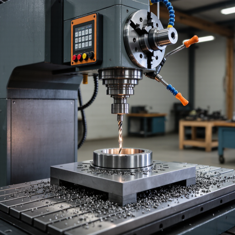
7 Tips to Choose the Best Deep Drill Machine?

Define Deep Drilling by the 10:1 Hole-Depth-to-Diameter Industry Ratio

7 Tips to Choose the Best Deep Drill Machine

Deep drilling usually means a hole with a depth-to-diameter ratio of at least 10:1. For example, a 200 mm deep hole may require a 20 mm diameter. This ratio matters because long holes increase deflection, heat, chip blockage, and alignment errors. In practical machining, the opening can look accurate while the bottom drifts slightly.

Tip 1: Match the machine to the ratio, material, and required tolerance. A rigid frame, stable spindle, and controlled feed reduce vibration. Tip 2: Check the cooling and chip-removal system. Deep holes need steady coolant flow and a clear path for chips. Dry cutting may create heat quickly. Tip 3: Review real cutting data, not only catalog claims. Ask for hole-depth tests using similar steel, aluminum, or difficult alloys. Experience shows that a machine performing well at 8:1 may struggle at 15:1.

Tip 4: Examine tool guidance and spindle runout. Small alignment errors become larger down a deep hole. Tip 5: Confirm that the machine supports pecking, gun drilling, or other suitable methods. Tip 6: Measure the finished hole with reliable gauges, including straightness and diameter checks. Tip 7: Consider operator training and maintenance access. A technically strong machine can still produce poor results when setup habits are inconsistent. I would also challenge one assumption: the 10:1 ratio is a useful industry boundary, not a guarantee of quality. Material hardness, tool geometry, coolant pressure, and tolerance may demand a more capable system.

7 Tips to Choose the Best Deep Drill Machine

Deep drilling is commonly defined by an industry hole-depth-to-diameter ratio of at least 10:1. The chart below shows the corresponding hole depth for a 10 mm diameter hole.

As the depth-to-diameter ratio increases, chip evacuation, coolant delivery, tool rigidity, spindle accuracy, and machine stability become increasingly important. When selecting a deep drill machine, compare its rated drilling depth, coolant pressure, guide support, accuracy, and compatibility with the required hole diameter and material.

Match Machine Type to Hole Diameter, Depth, Material, and HRC Hardness

Choosing a deep drill machine starts with the hole, not the machine catalog. For diameters below 20 mm, a gun-drilling system often offers better chip control and straightness. Larger holes may require BTA or ejector drilling, especially when depth exceeds 20 times the diameter. Measure the complete depth, including breakthrough and chip clearance. A 12 mm hole, 300 mm deep, demands different rigidity than a 60 mm hole of equal depth. It is easy to underestimate that difference.

Material changes the decision. Aluminum needs sharp geometry and efficient coolant evacuation, while stainless steel requires stable feed control and strong heat removal. For hardened steel, check the Rockwell C value under ASTM E18. Materials above roughly 45 HRC may need carbide tooling, special coatings, or pre-machining. Do not rely on hardness alone. Alloy content, interrupted surfaces, and residual stress can change tool behavior. In practice, a test hole often reveals more than a specification sheet.

Machine power must match cutting torque, coolant pressure, and spindle speed. The IEA’s Energy Efficiency 2023 report estimates motor-driven systems use about 53% of global electricity, so pump and spindle efficiency deserve attention. ISO 230-2 also provides a useful framework for checking positioning accuracy. A perfect chart cannot replace inspection. Measure hole size, straightness, surface finish, and tool wear after the first batch. That first result may challenge your original choice.

Check Spindle Torque, Feed Control, and ISO 230-2 Positioning Accuracy

Choosing a deep drill machine requires more than checking maximum drilling depth.

Real performance appears when torque, feed control, and positioning accuracy work together.

Tip 1: Check spindle torque across the working speed range. Peak torque alone can mislead. Ask for a torque curve and test a hole in the intended material.

Tip 2: Examine spindle rigidity. Hold a test bar and measure visible runout near the tool holder. Small errors become larger during deep drilling.

Tip 3: Match the spindle speed to the drill diameter and material. Excessive speed can create heat, vibration, and premature tool wear.

Tip 4: Test feed control at low, medium, and high rates. The machine should maintain steady movement without sudden stops or pressure spikes.

Tip 5: Confirm chip-breaking or pecking control. Poor timing can pack chips inside a narrow hole. That is risky for accuracy.

Tip 6: Request an ISO 230-2 positioning accuracy report. Check both repeatability and bidirectional positioning results, not only the best value.

Tip 7: Repeat the test after warm-up. Thermal drift may shift the hole position after several hours.

I have seen an accurate cold machine perform differently later.

No test is perfect. Record temperature, tool condition, workpiece setup, and measurement equipment before comparing results. A supplier should explain unusual readings clearly, rather than hiding them behind one impressive specification.

Evaluate Coolant Delivery: 20–70 bar Pressure for BTA Deep-Hole Systems

When choosing a deep drill machine, inspect coolant delivery before spindle power. In BTA deep-hole systems, pressure commonly ranges from 20 to 70 bar. That range is not a target by itself. Low pressure may leave chips packed around the cutting edge. Excessive pressure can stress seals, disturb chip control, and expose weak plumbing. Ask for measured pressure at the tool inlet, not only at the pump outlet. Pressure is lost through filters, hoses, valves, and long passages.

Match pressure with hole diameter, workpiece material, tool geometry, and drilling depth. Tough alloys often need stronger, steadier flushing. Softer materials may respond better to controlled flow than maximum pressure. Watch liters per minute too. Pressure without sufficient volume is misleading. During a trial cut, monitor the gauge, coolant temperature, chip shape, and surface finish. A stable stream should carry chips out continuously, without surging or foaming. Short interruptions matter. They can mark the bore.

Check whether the machine has separate filtration, an accessible reservoir, and alarms for low flow or pressure. Fine chips can quickly block a filter and reduce real delivery. Verify hose ratings, sealing quality, and emergency relief protection. I would also compare readings before and after the filter. The difference reveals system resistance. One imperfect assumption is common: higher bar always means faster drilling. It does not. A rigid machine with balanced coolant delivery may outperform a more powerful pump. Request a documented test using your material, diameter, depth, and tool. Generic demonstrations can hide the difficult part.

7 Tips to Choose the Best Deep Drill Machine? – Evaluate Coolant Delivery: 20–70 bar Pressure for BTA Deep-Hole Systems

Tip Evaluation Dimension Recommended Specification or Check Why It Matters in BTA Drilling Practical Acceptance Target
1 Coolant pressure range Select a high-pressure coolant system adjustable from approximately 20 to 70 bar, subject to tool diameter, material, and tooling instructions. BTA systems deliver coolant through the tool and remove chips through the drill head. Adequate pressure supports chip evacuation and stabilizes the cutting zone. Pressure remains stable at the required flow rate during continuous drilling, without excessive pulsation.
2 Coolant flow capacity Check the pump curve for flow at operating pressure; do not assess the pump by pressure alone. Confirm compatibility with the selected BTA head and bore diameter. Larger holes and higher material-removal rates generally require greater coolant volume to carry chips through the return passage. The system meets the tooling supplier’s specified flow while maintaining the required pressure at the drill head.
3 Filtration and chip separation Use a tank and filtration arrangement designed for continuous chip loading, with accessible filters, chip collection, and differential-pressure monitoring. BTA drilling produces chips that can restrict coolant passages, damage pumps, or cause pressure loss if they are not removed efficiently. A visible pressure-drop indicator or alarm identifies filter loading before coolant delivery becomes inadequate.
4 Pressure and flow monitoring Require calibrated pressure and flow gauges, plus low-pressure and low-level alarms integrated with the machine control. A sudden pressure change may indicate a blocked tool passage, leaking seal, empty tank, or pump problem. Early detection helps prevent tool damage. The machine can stop or feed-hold automatically when coolant pressure or flow falls below the programmed limit.
5 Coolant temperature control Evaluate tank volume, heat-exchanger capacity, temperature sensing, and the expected heat load from spindle power and cutting time. Temperature changes can affect coolant viscosity, tool life, dimensional stability, and the consistency of deep-hole drilling. Coolant temperature remains within the tooling and workpiece process limits during the longest planned production cycle.
6 Seals, rotary joints, and return path Verify that seals, rotary unions, hoses, and chip-return passages are rated for the selected pressure, coolant type, temperature, and rotational speed. The BTA circuit depends on reliable separation between pressurized supply and chip-laden return flow. Leakage can reduce pressure and create safety risks. No visible leakage, hose swelling, abnormal seal wear, or return-line restriction is present during a full-pressure test.
7 Coolant quality and maintenance Use a coolant suitable for the workpiece and tooling, and define controls for concentration, pH, contamination, tramp oil, and microbial growth. Poor coolant condition can increase corrosion, foam, odor, residue, tool wear, and filter loading, reducing drilling reliability. Routine checks are documented, concentration is maintained within the coolant supplier’s specified range, and tank cleaning intervals are defined.
Selection note: The 20–70 bar range is a practical evaluation range for high-pressure BTA coolant delivery, not a universal operating setting. Final pressure and flow must be matched to the drill diameter, workpiece material, tooling design, coolant, and applicable safety requirements.

Compare Chip Evacuation, Tool Life, Automation, Safety, and Total Cost

Choosing a deep drill machine demands more than checking maximum depth. Start with chip evacuation, because packed chips can score the bore and raise cutting pressure. Compare coolant delivery, flute geometry, and chip conveyor capacity under your real material. Ask for test cuts using your diameter, depth, and production feed. A clean exit matters. I once underestimated a small coolant-flow change; the hole looked acceptable, but tool wear doubled.

Tool life should be measured per hole, not by optimistic catalog hours. Record edge wear, cycle time, surface finish, and rejected parts. A machine with automatic tool monitoring can detect abnormal load before a broken tool damages the workpiece. Automation reduces repetitive handling, yet sensors need calibration and operators need training. Never treat guarding, interlocks, emergency stops, and chip containment as optional. Watch the first production run closely.

Calculate total cost across the machine’s useful life. Include tooling, coolant, electricity, maintenance, programming, downtime, and scrap. A lower purchase price may hide expensive manual loading or frequent spindle repairs. Compare recovery time after alarms, spare-part availability, and service response in writing. Request references from shops drilling similar alloys and depths. Be skeptical of perfect demonstrations. Real floors are noisy, variable, and occasionally untidy. That is where reliability proves itself.