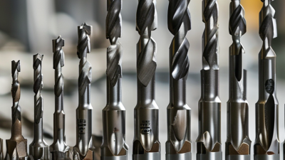
How to Choose Carbide Tipped Drill Bits?
Choosing Carbide Tipped Drill Bits is not simply a matter of selecting the hardest available tool. The correct choice depends on the workpiece, drilling depth, machine stability, and required hole quality. A bit that performs cleanly in cast iron may chip quickly in stainless steel. The difference can be only a few degrees of point geometry or an unsuitable feed rate.
Dr. Milton C. Shaw, a respected authority on machining science, stated, “Metal cutting is a complex physical phenomenon.” His observation remains valuable when comparing carbide grades, tip angles, coatings, and shank designs. Carbide offers excellent hardness and wear resistance, but it is also brittle. Excessive vibration, interrupted cutting, or a slightly misaligned chuck can fracture the tip without warning. Harder is not always better.
A reliable selection begins with the material. Aluminum usually benefits from polished flutes and generous chip space. Hardened steel may require a stronger point, suitable coating, and controlled coolant delivery. Check the manufacturer’s speed and feed chart, then adjust carefully for machine rigidity. Watch the chips. Powder-like debris, blue edges, or a high-pitched squeal signals trouble.
Small details matter. A pilot hole can reduce wandering. A rigid setup prevents sudden impact. Yet charts are not perfect for every workshop. Real conditions differ, and that deserves honest attention. The best Carbide Tipped Drill Bits are chosen through technical guidance, measured testing, and a willingness to reconsider the first assumption.
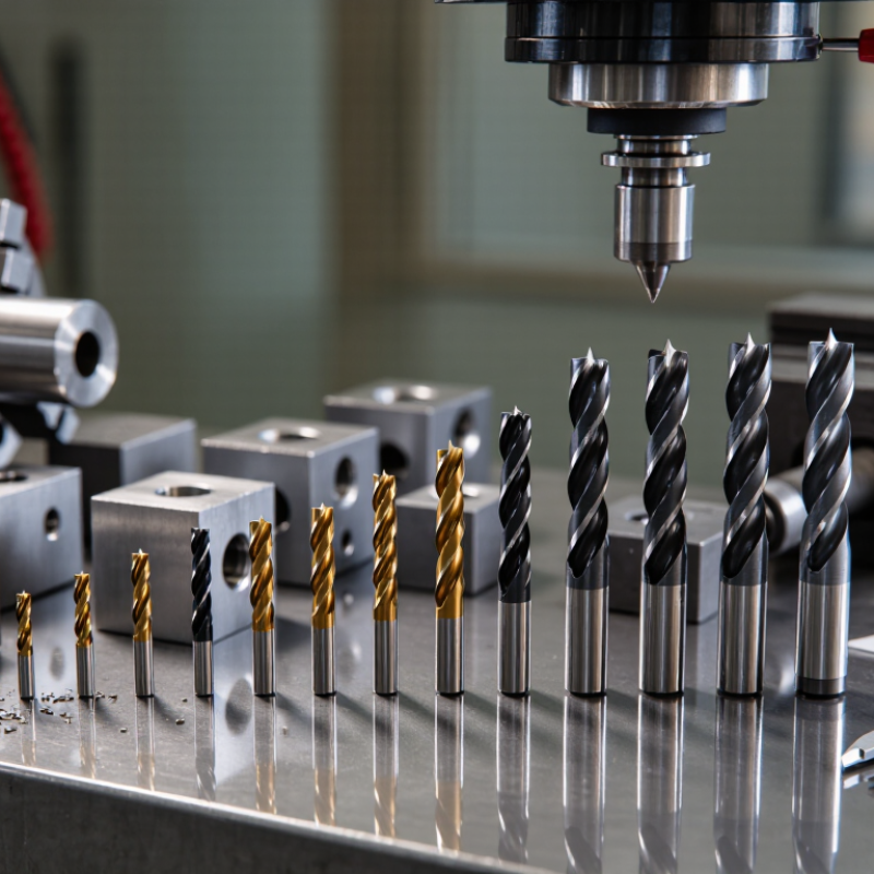
Carbide-Tipped Drill Basics: WC–Co Tips Reach 1,500–2,200 HV
How to Choose Carbide Tipped Drill Bits?
Carbide-tipped drill bits use a tough steel body with a WC–Co cutting tip. WC means tungsten carbide, while Co means cobalt binder. Depending on grain size, cobalt content, and testing method, the tip may reach about 1,500–2,200 HV. This high hardness helps resist abrasion when drilling masonry, fiber-reinforced materials, cast iron, and some non-ferrous metals. Hardness alone does not guarantee performance. A poorly brazed tip can fail before it wears.
Check the workpiece before choosing the bit. Dense concrete needs a reinforced tip and a suitable masonry point. Laminated composites need sharp edges and controlled pressure, or the surface may splinter. For metal, confirm the flute design, point angle, and recommended cutting speed. Not every carbide-tipped bit suits hardened steel. That assumption can be costly.
Look closely at the tip alignment. It should appear centered, smooth, and firmly joined to the shank. Excessive runout creates uneven cutting and vibration. In practical use, steady feed pressure usually works better than forcing the bit. Keep the bit cool when the material and tool design require it. I have seen operators blame carbide quality after using a dull bit with excessive speed. The real problem was often heat. A small mistake matters. Even premium hardness cannot repair poor setup, unstable clamping, or a worn cutting edge.
WC–Co carbide hardness generally decreases as cobalt binder content increases. Fine-grained grades with approximately 3–6% cobalt can reach about 1,500–2,200 HV, providing high wear resistance for drilling abrasive materials. Higher cobalt content improves toughness but typically lowers hardness.
Choose Point Geometry: 118° for General Work, 135° for Hard Metals
How to Choose Carbide Tipped Drill Bits?
Choosing the correct point geometry is often more important than selecting a drill by appearance. A 118° point suits general work, especially mild steel, aluminum, wood composites, and routine workshop drilling. Its sharper profile starts easily and produces a steady cutting action. I usually choose it for clean, moderate-depth holes where the material is not unusually hard.
A 135° point is better for hard metals, stainless steel, and tough alloys. Its flatter shape resists walking and reduces edge chipping under pressure. The split-point design, when available, can improve starting accuracy on polished surfaces. However, geometry alone cannot solve every drilling problem. Speed, feed pressure, cooling, and tool rigidity still matter. I have seen a well-chosen bit fail because the operator pushed too hard. That mistake is easy to repeat.
Tips: Match the point angle to the material, not just the hole size. Use a firm setup and mark the center before drilling. For hard metals, begin slowly and apply consistent pressure. Keep the bit cool with a suitable cutting fluid when the material allows it. A 135° point may last longer, but it can feel less aggressive in softer materials. Test on scrap first. Small trials often reveal problems before they become expensive. Check for heat discoloration, unusual vibration, or a squealing sound. These signs suggest excessive speed, poor alignment, or a dull cutting edge.
Match Carbide Grades: 6%–12% Cobalt Balances Wear and Toughness
How to Choose Carbide Tipped Drill Bits?
Carbide grade selection starts with cobalt content. A 6% cobalt grade is harder and resists abrasive wear well. It suits stable drilling in cast iron, hardened alloys, and abrasive composites. However, lower cobalt content can reduce toughness. A small impact may chip the cutting edge.
An 8%–10% cobalt grade often provides a practical balance. It handles regular production drilling, moderate vibration, and changing workpiece conditions. For interrupted cuts or less rigid machines, 10%–12% cobalt offers greater toughness. The edge may survive brief shock loads better. The trade-off is faster wear in highly abrasive material.
Watch the actual cutting behavior. A sharp, polished edge may reduce friction, but excessive feed can still fracture the tip. Use firm workholding, suitable coolant, and a controlled feed rate. Match the bit diameter and point geometry to the hole depth. Long, deep holes need reliable chip evacuation.
Test one bit first.
In my experience, cobalt percentage alone does not decide tool life. Machine alignment, brazing quality, cutting speed, and operator technique matter just as much. A tougher grade is not automatically better. It may wear too quickly in a stable, abrasive cut. Conversely, a hard grade can fail suddenly when vibration increases. Review the chips, edge condition, and hole finish after each trial. That evidence is more dependable than a specification chart alone.
How to Choose Carbide Tipped Drill Bits? - Match Carbide Grades: 6%–12% Cobalt Balances Wear and Toughness
| Cobalt Content |
Typical WC Grain Size |
Typical Hardness |
Typical Transverse Rupture Strength |
Wear Resistance |
Toughness and Impact Resistance |
Recommended Drilling Applications |
Selection Guidance |
| 6% Co |
Fine to medium-fine |
Approximately 92.5–94.5 HRA |
Approximately 2.0–2.6 GPa |
Very high; retains a sharp cutting edge during abrasive drilling |
Moderate; more sensitive to vibration, interrupted cuts, and sudden impacts |
Cast iron, hardened non-ferrous alloys, abrasive composites, glass-filled plastics, and stable drilling setups |
Choose when wear life and dimensional stability are more important than impact resistance. |
| 8% Co |
Fine to medium-fine |
Approximately 91.5–93.5 HRA |
Approximately 2.2–2.9 GPa |
High; suitable for general-purpose carbide-tipped drilling |
Good; tolerates normal machine vibration and moderate variation in workpiece hardness |
General steel, cast iron, stainless steel with controlled cutting conditions, and non-ferrous metals |
Choose for a strong balance between cutting-edge wear resistance and everyday durability. |
| 10% Co |
Medium-fine to medium |
Approximately 90.5–92.5 HRA |
Approximately 2.4–3.2 GPa |
Good; adequate for demanding general machining |
Very good; better resistance to chipping and intermittent loading than lower-cobalt grades |
Structural steel, alloy steel, stainless steel, castings, and drilling with less rigid fixturing |
Choose when a balanced combination of wear resistance, toughness, and reliability is required. |
| 12% Co |
Medium to coarse |
Approximately 89.5–91.5 HRA |
Approximately 2.7–3.5 GPa |
Moderate to good; generally lower than 6%–8% cobalt grades |
High; provides improved resistance to shock, vibration, and edge chipping |
Interrupted drilling, rough castings, difficult-to-fixture components, tough steels, and applications with impact loading |
Choose when toughness and breakage resistance are more important than maximum wear life. |
Technical note: The values shown are typical reference ranges for conventional tungsten-carbide/cobalt cemented carbide. Actual hardness and strength depend on cobalt distribution, tungsten-carbide grain size, porosity, sintering conditions, and the finished tool geometry. Higher cobalt content generally improves toughness and impact resistance, while lower cobalt content generally improves hardness and wear resistance.
Set Cutting Conditions: Follow Manufacturer RPM, Feed, and Coolant Data
Choosing carbide-tipped drill bits starts with matching the tool to the workpiece, hole depth, and machine rigidity. Carbide tips resist heat and wear, but they can chip under vibration or interrupted cutting. I check the manufacturer’s recommended RPM, feed rate, and coolant method before drilling. These figures are not decoration. They reflect tested cutting geometry and material behavior.
Calculate RPM from the published cutting speed and drill diameter. Use the recommended feed per revolution, then reduce it cautiously for deep holes, weak setups, or poor alignment. Start conservatively. A rigid machine may handle the listed rate, while a smaller benchtop machine may not. I once used a standard setting on a flexible fixture and produced a rough, bell-mouthed hole. The tool was suitable; my setup was not.
Coolant must reach the cutting edges, not merely wet the surface. Follow the specified coolant type, pressure, and delivery direction. For deep holes, withdraw the bit as instructed to clear chips and control heat. Watch the chips. Powdery chips, rising spindle noise, or discoloration can signal incorrect conditions. Stop and reassess before damage spreads. Record the actual RPM, feed, material hardness, and hole quality after each trial. Manufacturer data remains the authority, but real cutting results deserve careful review.
Check Tool Quality: Control Runout, Edge Integrity, and Shank Compatibility
When choosing carbide-tipped drill bits, tool quality deserves close inspection. A sharp cutting edge cannot compensate for excessive runout. I check the bit in the actual holder, not only on the workbench. A dial indicator can reveal movement that is invisible to the eye. For precision drilling, I generally look for runout below 0.02 mm near the cutting end. The acceptable value depends on the machine and hole tolerance.
Edge integrity matters just as much. Under magnification, the carbide should show an even profile without chipped corners, hairline cracks, or uneven brazing. Small edge damage can produce oversized holes and rough walls. I also rotate the bit under strong light to compare both cutting lips. They should appear balanced. Still, visual inspection is imperfect. A short test hole in similar material often exposes problems faster than inspection alone.
Shank compatibility is easy to overlook. Confirm the shank diameter, usable length, holder type, and machine capacity before buying. A loose fit can increase vibration and damage the edge. An oversized shank may not enter the chuck at all. Clean the holder, tighten it correctly, and check the bit again for runout. I once blamed a drill for poor accuracy when the real problem was a worn chuck. That mistake changed my inspection routine. Tool quality includes the bit, the connection, and the conditions around it.